
See the feedback for group 2 today from our online class. This feedback will benefit all students.
https://youtu.be/mRtymw-zTgQ
© 2022 Vedesh Kungebeharry. All rights reserved.
See the feedback for group 2 today from our online class. This feedback will benefit all students.
https://youtu.be/mRtymw-zTgQ
© 2022 Vedesh Kungebeharry. All rights reserved.
Thus far it is possible that we’ve made the assumption that a process usually runs to completion and then the OS runs other processes. As indicated in our process management note/discussion we now know this to be false.
It is possible for an OS to be implemented as a timing mechanism, switching between each process after say 100 instructions being executed. In theory, this is a good first approach if all instructions are executed in a very short and equal timeframe.
Below, we represent how this can be accomplished by observing what the cpu processes assuming each instruction takes about 1 second for 2 processes, P1 and P2:
| Order of execution | Process/operation category | Instructions executed | Time taken (s) |
| 1 | I/O | I/O for OS and P1 | 2 |
| 2 | P1 | 100 lines from P1 | 100 |
| 3 | I/O | I/O for OS and P2 | 2 |
| 4 | P2 | 100 lines from P2 | 100 |
| . . . . . | . . . . . | . . . . . | . . . . . |
| 501 | I/O | I/O for OS and P1 | 2 |
| 502 | P1 | 100 lines from P1 | 100 |
| 503 | I/O | I/O for OS and P2 | 2 |
| 504 | P2 | 100 lines from P2 | 100 |
| . . . . . | . . . . . | . . . . . | . . . . . |
In practice though, a single instruction from a running process can be waiting or very long, such as when the instruction requires data be read from a secondary storage medium. Data access on secondary storage is very slow. Let us assume that P1 has a few instructions that require some data access. Our table now becomes:
| Order of execution | Process/operation category | Instructions executed | Time taken (s) |
| 1 | I/O | I/O for OS and P1 | 2 |
| 2 | P1 | 100 lines from P1 | 1500 |
| 3 | I/O | I/O for OS and P2 | 2 |
| 4 | P2 | 100 lines from P2 | 100 |
| . . . . . | . . . . . | . . . . . | . . . . . |
| 501 | I/O | I/O for OS and P1 | 2 |
| 502 | P1 | 100 lines from P1 | 1200 |
| 503 | I/O | I/O for OS and P2 | 2 |
| 504 | P2 | 100 lines from P2 | 100 |
| . . . . . | . . . . . | . . . . . | . . . . . |
We observe in this analogy that p1 runs for a total of 1502 seconds P2 for 102, P1 for 1202 seconds, P2 for 102 seconds.
To the end user, It appears as if BOTH processes are running slowly, in the long run, p2 can appear to be running in slow motion!
To solve this problem, we could use a system of interrupts, i.e, interrupt the CPU whenever we anticipate a waiting period (for whatever reason I/O, system errors, device errors etc.)
In our analogy, every time P1 needs to wait on data from secondary access, we could put the rest of P1 in a waiting/blocked state and start processing P2. When the hardware is finished gathering the data for P1, it could interrupt the execution of P2 and return control to P1.
Omitting IO from the OS, An illustration of this example is shown below:
(Assume that instructions for p1 are executed in 1 second intervals until an instruction needing secondary data access is reached)
P1’s instruction include:
49 short instructions then,
1 long access instruction then,
24 short instructions then,
1 long access instruction, then
25 short instructions
| Order of execution | Process/operation category | Instructions executed | Time taken (s) |
| 1 | P1 | 50 lines from P1 | 50 |
| 2 | OS | (P1 Blocked), | – |
| 3 | P2 | 100 lines from P2 | 100 |
| 4 | P2 | 100 lines from P2 | 100 |
| 5 | P2 | 100 lines from P2 | 100 |
| 6 | P2 | 50 lines from P2, interruption occurs | 50 |
| 7 | P1 | 25 lines from P1 | 25 |
| 8 | OS | (P1 Blocked), | – |
| 9 | P2 | 50 lines from P2 | 50 |
| 10 | P2 | 100 lines from P2 | 100 |
| 11 | P2 | 100 lines from P2 | 100 |
| 12 | OS | Interruption occurs to return accessed data to P1 | – |
| 13 | P1 | 25 lines from P1 | 25 |
| 14 | P2 | 100 lines from P2 | 100 |
| . . . . . | . . . . . | . . . . . | . . . . . |
We now observe both processes running efficiently with no excessive wait times.
© 2022 Vedesh Kungebeharry. All rights reserved.
Multiple programs are usually executed concurrently as processes (running programs). A bit of code from each process is executed at a time on the processor so that all processes are continually executed until system shutdown or they have completed their task and exit.
The operating system (OS) is programmed to start the execution of programs and manage their execution by putting them into different states. Note that the programs can be application programs intended for the end user or system programs used for self management (e.g memory management)
Discussion:
Running – The process is currently being executed
Ready – A previously interrupted process that can be expected to resume.
Waiting/blocked – a process that has been put to wait by the cpu or is waiting on a slower operation (I/O or request for data)

© 2022 Vedesh Kungebeharry. All rights reserved.
This is the process of loading and executing the basic instructions to load the operating system to bring the system to a fully functional state to be used for its intended purpose (initiated either by the user powering on the system or an autonomous system system e.g a network device , typically a router. See wake on lan) . For modern day systems, these instructions are usually hardcoded in the EEPROM.
2023-09-15 – Added wake on LAN, and detailed to the initiation of the device.
© 2022 Vedesh Kungebeharry. All rights reserved.
Exercise 1 : Modify your code from the previous example to use floating point numbers 5.1 and 6.1
Exercise 2:
Observe what is output when %d is changed to each of the following, one at a time:
%d for int
%f for float
%lf for double
%c for char
%s for string
https://youtu.be/Be_QtiweYTY
You can download the files here: https://drive.google.com/file/d/1nVXCOXTJkPYNSs2jDwxGGbz9mvuKooDK/view?usp=sharing
#include <stdio.h>
#include <stdlib.h>

int main()
{
   //declare and identify variables
   float a,b;
   float c;

   //Initialize the variables
   a=5.1;
   b=6.1;

   //Perform processing c <-- a+b
   c=a+b;

   printf("The sum of %.1f and %.1f is %.f \n", a,b,c);


}
© 2021 Vedesh Kungebeharry. All rights reserved.
Exercise: Modify your previous code to output results using printf()
https://youtu.be/YE0V_XLuOx8
You can download the file used in the video here: https://drive.google.com/file/d/1A4oCHsdXW0Ab7ox-T_zXi3eVmrQkXoic/view?usp=sharing
#include <stdio.h>
#include <stdlib.h>

int main()
{
   //declare and identify variables
   int a,b;
   int c;

   //Initialize the variables
   a=5;
   b=6;

   //Perform processing c <-- a+b
   c=a+b;

   printf("The sum of %d and %d is %d \n", a,b,c);


}
© 2021 Vedesh Kungebeharry. All rights reserved.
https://youtu.be/nfGwWUIZDaY
Download the files here: https://drive.google.com/file/d/15PfdndUqvnd_fLYPzctsgZMG4I9oSYtx/view?usp=sharing
#include <stdio.h>
#include <stdlib.h>

int main()
{
   //declare and identify variables
   int a,b;
   int c;

   //Initialize the variables
   a=5;
   b=6;

   //Perform processing c <-- a+b
   c=a+b;


}
© 2021 Vedesh Kungebeharry. All rights reserved.
*Using Codeblocks 17.12
1. Create a new Project

2.Select “Console Application” and click on go.
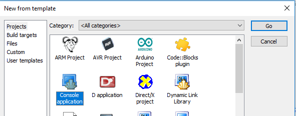
3.Select “C” and click next.

4. Give your project a title and optionally select a folder where you want the project to be created. In this case we use “Upper camel case”` : “0001-MyFirstProgram”

5.Leave all settings as default and choose finish:

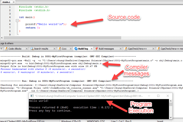
6. Open main.c from the tree on the left. [1] Expand sources, [2]then double click on “main.c”.

7. Click on Build, and choose build and run.

8. Your code is now built to an executable file, and the program is executed in the console window:
You can download the project here:
https://drive.google.com/drive/folders/1-oDom6OVimkNZeBACsJs9FZ0byhsNXHv?usp=sharing
The code is shown below:
#include <stdio.h>
#include <stdlib.h>

int main()
{
    printf("Goodbye world!");
    return 0;
}
© 2021 Vedesh Kungebeharry. All rights reserved.
A multiplexer is a combinational circuit having many inputs which allows for the outputting a single data input at a time by using selection input lines. A multiplexer has 2n data input lines , n select input lines and a single output.
Teacher describes a remote control with 2 buttons that can be toggled on and off to switch between 4 channels

The truth table is shown below:
| s1 | s2 | Output at F |
|---|---|---|
| 0 | 0 | x1 |
| 0 | 1 | x2 |
| 1 | 0 | x3 |
| 1 | 1 | x4 |
Note that the data from any input line can be either a 0 or 1 instantaneously depending what the input at a the time. For example, let us consider the situation where over the next 4 cycles of execution on a cpu that
The resulting output at f over the four cycles are 0000.
That is, two bits of data from x1, then two bits of data from x2.
In sequence , we selected x1 for 2 consecutive cycles, then x2 for another 2 consecutive cycles.
Using the Oxford English Dictionary, the original spelling is multiplexer, as evidenced by it’s widespread use. However it’s use in quotation is as early as 1961, the spelling as multiplexor appeared in quotation in 1957.
Despite this, It’s generally accepted that the original spelling is multiplexer, and multiplexor should be considered a variation on the.
See:
2023/11/25-
Added Special Note on Spelling: MultiplexEr or MultiplexOr ?
Changed Main spellings from multiplexor to multiplexer in note and URL
© 2021 Vedesh Kungebeharry. All rights reserved.
This post is used for discussion in class.
Teacher draws a SR latch using NOR gates with top gate as g1 and bottom gate as g2.

Teacher draws a truth table for quick reference:
| A | B | A NOR B |
|---|---|---|
| 0 | 0 | 1 |
| 0 | 1 | 0 |
| 1 | 0 | 0 |
| 1 | 1 | 0 |
No machine-readable author provided. Arturo Urquizo assumed (based on copyright claims)., CC BY 3.0 <https://creativecommons.org/licenses/by/3.0>, via Wikimedia Commons
© 2021 Vedesh Kungebeharry. All rights reserved.
